Thermal Management Design for Charger: Reduce Temperature Rise & Extend Service Life
1. Main Heat Sources Inside the Charger
Heat inside a Charger comes from switching loss and conduction loss of power devices, together with copper loss and core loss in transformers. Power MOSFETs, diodes and electrolytic capacitors are the main heat-generating components. Higher load increases power loss of the Charger and raises temperature of the housing and internal parts.
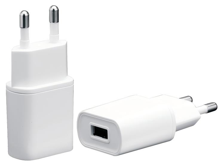 Without effective heat dissipation, electrolyte inside electrolytic capacitors evaporates rapidly. Main controller ICs and MOSFETs under long-term high-temperature stress suffer parameter drift. In severe cases, high temperature softens plastic housing and violates safety limits, invalidating product certifications. Ambient conditions greatly affect thermal performance. Enclosed housings and tight mounting spaces trap heat significantly. B-side hardware often runs continuously, requiring stricter steady-state temperature limits for the Charger than consumer-grade short-use products.
2. Comparison of Mainstream Heat Dissipation Structures for Charger
Two common cooling solutions are used for Charger: natural convection and housing thermal conduction. Fans are rarely integrated.
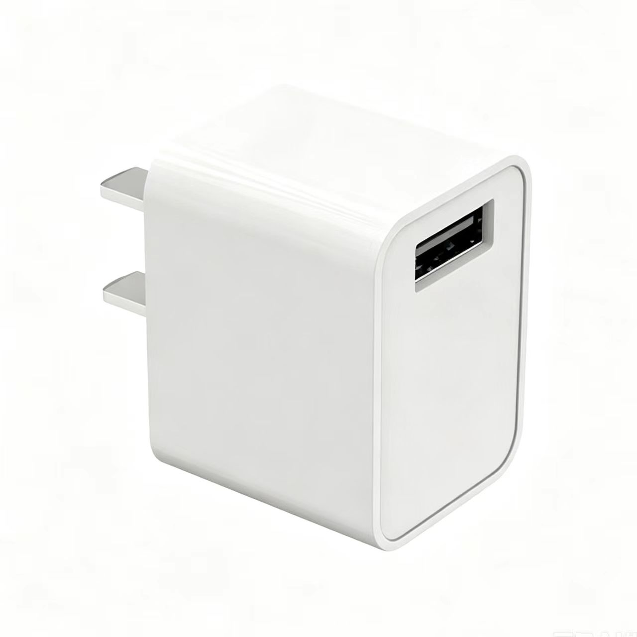 Natural convection relies on housing vents and air flow to dissipate heat. It features simple structure and lower cost. This solution fits low-to-medium power Charger in well-ventilated environments. Its limitation is weak cooling in sealed enclosures; temperature rises sharply under high ambient temperature.
Housing thermal conduction uses high thermal conductivity plastic or metal housing to transfer heat from internal components to the outer surface. It delivers stronger cooling capacity, suitable for industrial and high-power Charger. Metal housing requires extra insulation to prevent electric leakage and comes with higher material cost.
Select cooling architecture based on end-device mounting environment. For equipment installed inside sealed cavities, Charger relying only on natural convection cannot sustain long full-load operation.
3. Standard Temperature Rise Test for Charger
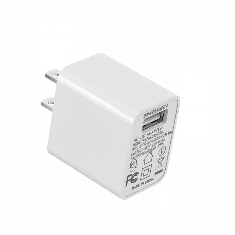
Temperature rise test follows IEC 62368, carried out in a 25℃ constant-temperature chamber. Run the Charger at full rated load for more than 4 hours until thermal equilibrium. Attach thermocouples to MOSFETs, transformers, capacitors and housing to capture steady-state temperature readings.
Tests cover room temperature and maximum rated ambient temperature. Many overseas customers deploy hardware at 40℃ ambient, which reduces thermal margin of the Charger.
Pass criteria: component temperature stays within datasheet limits and housing touch temperature meets safety requirements. Keep power on after test to monitor continuous temperature climbing. If temperature exceeds limits, rework PCB layout and rearrange component placement to reduce heat concentration.
4. Thermal Design Optimization to Reserve Sufficient Temperature Margin
Several practical engineering methods optimize thermal performance of the Charger.
First, optimize PCB layout and spread heat-generating power components across the board to avoid heat accumulation in one area.
Second, adopt low-loss power semiconductors to cut heat generation at the source.
Third, design housing vents properly, keep safety clearance while enabling air convection.
Fourth, select high-temperature-rated electrolytic capacitors and plastic housing to raise component thermal tolerance.
B-side projects should not design right at temperature limits. Reserve more than 10℃ thermal margin to handle ambient temperature fluctuation and component parameter variation.
5. Mass Production Control for Consistent Temperature Performance
Lock the BOM of the Charger during mass production. Power devices, transformers, capacitors and housing material cannot be changed arbitrarily. Component replacement alters power loss and temperature profile. Any material revision requires full temperature rise re-testing.
Include temperature rise in incoming sampling. Pull samples from each batch for full-load thermal equilibrium test and verify readings at all measurement points. Archive complete test reports for overseas market inspection to prove the Charger complies with safety temperature requirements.
Conclusion
Thermal management of the Charger dominates long-term reliability, and excessive temperature rise is a top cause of field failures for overseas projects. B-side buyers sourcing a Charger should review full-load steady-state thermal reports instead of only checking rated specs, select cooling solutions matching end mounting conditions and reserve enough thermal margin. Strict material control during mass production ensures consistent temperature performance across batches. If you need custom thermal design and pre-compliance temperature testing, Sen Shu Qiang designs cooling schemes for the Charger based on operating conditions and delivers full thermal test reports. Feel free to contact us for project discussion.